Research on the jitter of sheet metal parts during robotic transfer
With the vigorous development of China's manufacturing industry, the trend of mechanization and automated production is becoming more and more obvious, and the use of robots in the production process is becoming more and more frequent. Because the robot has the characteristics of high stability, high safety factor, high production efficiency, stable product quality and cost saving, the robot is more and more widely used in the factory. The role of the manipulator in the processing of sheet metal parts is mostly the transfer of parts, and the degree of jitter in the process of transferring parts directly affects the accuracy of product positioning, thus affecting production efficiency and product quality (Figure 1), so research The problem of the jitter of the sheet metal during the transfer of the robot is of great significance.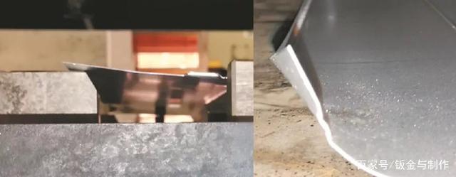 Figure 1 Position deviation due to jitter
Project Overview
The robot has problems in the process of transferring the sheet metal parts. The degree of vibration of the parts is different, and the displacement distance generated by the sheet metal parts is also different. When the displacement is larger than the positioning range of the equipment, it will cause the parts to be scrapped. In severe cases, it will cause serious safety accidents of equipment, robot damage and even personal injury. The following is a description of the air conditioning panel robot transfer line as an analysis object.
During the transfer of the robotic line, the degree of panel jitter is mainly affected by the characteristics of the robot, the part itself, and the part processing process. The characteristics of the part itself mainly include the material thickness of the part and the structure of the surface of the part.
Factor analysis
Robot
The robots commonly used in actual production include link-type robots, stand-alone robots, and three-dimensional robots. The portion of the take-up that is in direct contact with the part is called the robotic gripper. The mechanical grippers can be divided into adsorption type and gripping type according to different feeding methods. The panel manipulator line selected this time is configured as a stand-alone robot, using an adsorption robot gripper.
The suction type mechanical claw is connected to the robot through the suction cup bracket during operation, and reaches the designated position with the movement of the robot, and then the vacuum suction cup is used to remove the air pressure to realize the part (Fig. 2).
The main components of the suction robot grip include the suction cup mount, the suction cup bracket, the suction cup fitting and the vacuum suction cup (Fig. 3).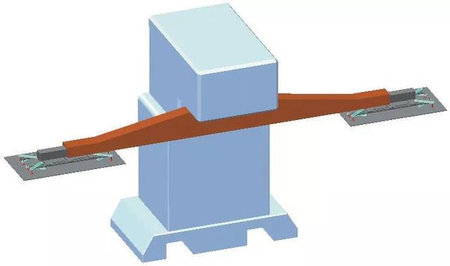 Figure 2 Free-standing robot
Through the understanding of the structure and working principle of the above-mentioned adsorption type mechanical gripper, it can be seen that the adsorption stability of the product of the adsorption type mechanical gripper under the constant pressure depends on the number and position of the vacuum suction cup. That is to say, by adding the suction cup fitting and the vacuum suction cup in the middle of the manipulator claw, the degree of jitter can be greatly reduced by controlling the range of the jitter. When the panel adopts four sets of suction cup fittings and vacuum suction cups in the production process, the problem of panel parts shaking often occurs (Fig. 4), and when six sets of suction cup fittings and vacuum suction cups are used, the problem of panel parts shaking is solved (Fig. 5). ).
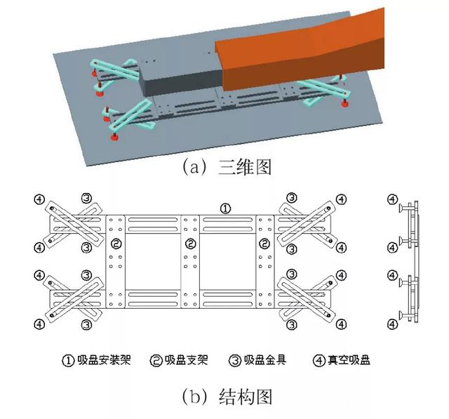 Figure 3 Mechanical gripper components
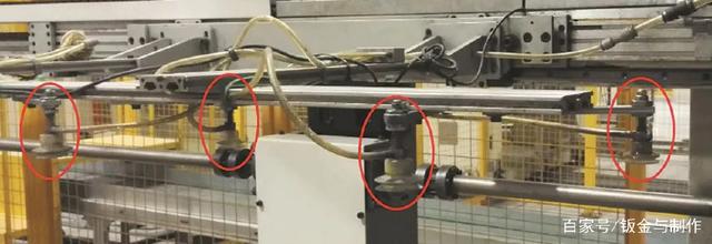 Figure 4 Four sets of suction cups and vacuum cups
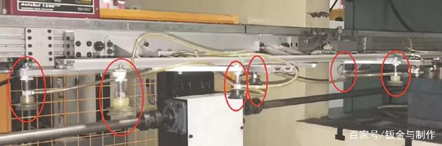 Figure 5 Six sets of suction cups and vacuum cups
Material thickness of the part
For the same size of the panel material, as the thickness of the part material is gradually increased, the mechanical properties of the part will gradually increase, and the degree of jitter of the panel will gradually decrease until slight jitter occurs without affecting normal production. However, reducing the jitter by increasing the material thickness will cause problems such as an increase in the cost of raw materials and a waste of equipment adjustment. Even when the material reaches 4 mm or more, the processing will switch from cold rolling to hot rolling. The method is hardly used in actual production.
Part structure change
Parts can be strengthened by adding physical reinforcement structures to reduce the strength and stiffness of the part during transmission, and finally meet the requirements of normal production. In the production process of the panel, the more common physical structure reinforcement methods are to increase the bending reinforcement rib, the convex reinforced rib structure and the production process layout optimization.
(1) Bending ribs.
Bending ribs are a way of adding a short bend to the physical reinforcement structure at the long edge of the part. The function of the bending rib is to increase the tensile strength and torsional strength of the part through physical reinforcement, thereby increasing the stability of the part conveying process, and finally reducing the degree of jitter during the part conveying process (Fig. 6).
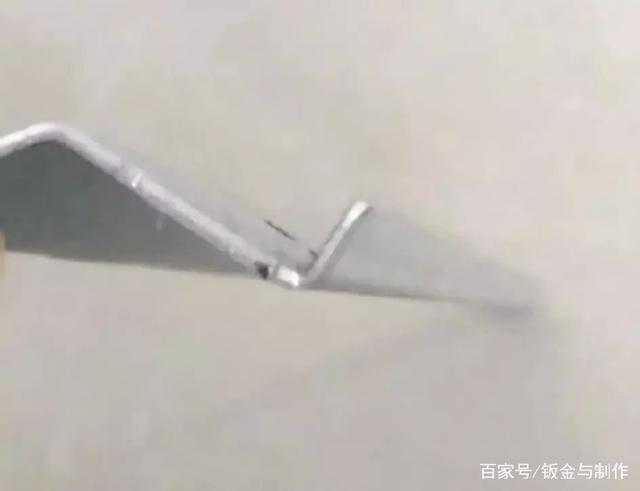 Figure 6 bending ribs
(2) Convex ribs.
The convex rib rib (bob rib) refers to a physical reinforcing structure added to the convex hull (stud) of the part. Convex ribs (stud ribs) are also used to increase the tensile strength and torsional strength of the parts by physical reinforcement, thereby increasing the stability of the parts during the transfer process, and finally achieving the purpose of reducing the degree of jitter during the part transfer.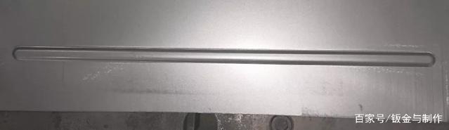 Figure 7 Adding a convex rib to the product
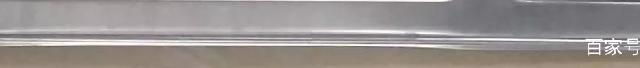 Figure 8 Adding convex ribs around the web
There are two ways to increase the convex ribs on the surface of the part. Convex ribs can be added directly to the product during the product design phase (Figure 7), or bulging ribs can be added around the web (Figure 8). In the subsequent process, the increased convex rib reinforcement may be removed according to the waste.
(3) Production process arrangement.
The production process is different, the mechanical properties of the parts are also different, and the degree of jitter of the parts during the transfer process is also greatly affected. If the punching process is excessively concentrated, stress concentration will result in distortion of the parts, which will reduce the flatness of the surface of the part, resulting in uneven suction of the vacuum chuck on the gripper jaws, and the parts will be shaken during the transfer.
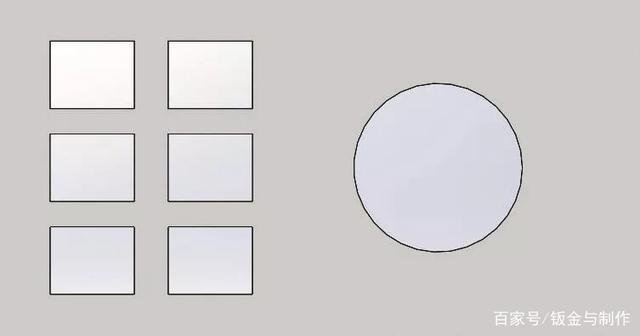 Figure 9 panel punching
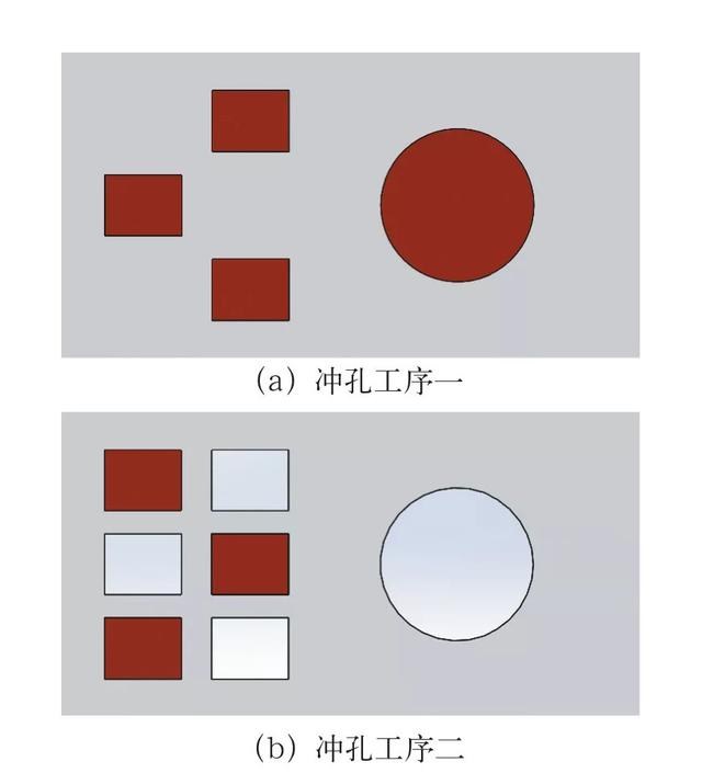 Figure 10 Improved punching process
If it is divided into two processes (Fig. 10), the stress generated by the production will be significantly reduced, and the strength of the part will be greatly improved.